
Basically it is not a technical blog, furthermore its language is hungarian but sometimes I make exception. Especially in cases when the subject expects wider interest than it can get in Hungary.
I am an amateur guitarist. I started this hobby when I was teenager. The lack of money and the fact that I lived in countryside forced me to learn how to build effect pedals for my guitar on my own. Of course I started with copying simple and well known circuits, but slowly my interest turned to create my own ideas. I made more than hundred distortion circuit, each of them differs from the others. Later I had enough of distortions so I made octaver, phaser and wah pedals either.
As for the wah pedals, I built almost every kind of design. I mean Crybaby variants, T filter schemas, Wien bridge circuits. Actually there was only two what I really liked. These are the original Crybaby and a very tricky T filter circuit. The second one had a huge advantage upon the Crybaby circuit. It did not need coil for working.
Coils around the necessary value (660 mH) are not easy to get, or at least it was the case where and when I made my attempts. Nowadays you can buy them on internet, but these are not that usual cheap component we have used to.
Due to I prefer a little bit more the sound of Crybaby I decided to modernize this circuit. First I set criteria for my redesigning experiment.
1. The circuit must be based on the original Crybaby circuit.
2. The coil must be replaced by an RC based solution. (R: resistors, C: capacitors - these are easy to get). Obviously we have to use gyrator.
3. As gyrators are built of OpAmp integrated circuit and RC parts, it is quite plausible that we should use OpAmps instead of transistors in the other part of the redesigned Crybaby circuit too.
4. As my capabilities to create cogwheel mechanic are extremely limited, the circuit should be tuned by optoelectronic way. Plausible by LED and photo resistor. Shadowing is way easier to make than turning a potentiometer's axis by foot via mechanic cogwheel and cog lat.
First let's see the original CryBaby circuit.
I decided replacing the transistors to opamps first. It is not as easy one can think. The original circuit has a tricky bias feedback from the collector of Q1 through the coil and the 1.5K resistor to Q1 base. In the same time the coil is part of a paralel RLC filter which consists of the 1.5K resistor, the coil, the 33k resistor and the 0.01uF capacitor which is connected to the emitter of Q2. That is not easy to transform this biased circuit to one that uses opamps. Well, it is not entirely true. Q2 is replacable without any trick. Let's see.
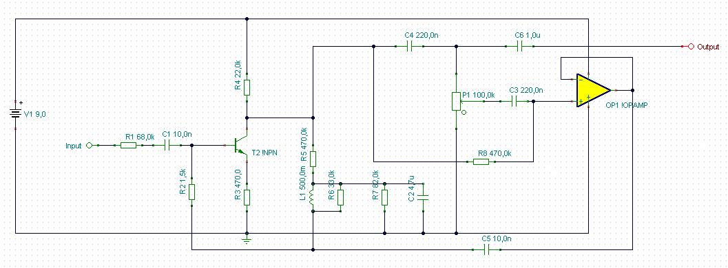
The remained transistor is though. Let's see why.
It's biased by negative feedback from its collector through the 470k resistor, the coil, and the 1.5k resistor. In these configuration - I mean with these emitter and collector resistors - its maximal gain is about 50x.
Other problem is that this biasing is good for a transistor but drives opamp out of its working range. Opamps usually should be biased to the center of their working voltage range. In this case we use 9V battery, so it means that practically we have to bias the opamps to 4.5V.
Furthermore replacing a transistor to an opamp - which amplifies the signal more than hundred thousand times instead of a couple of hundreds - we can be sure it will effect drastically the frequency characteristic..
I modeled the whole process in Tina - which is a very good and free (with limitations) circuit designer and modeling program. I found that after replacing the first transistor with an opamp the circuit did not work as bandfilter (this is the key of wah effect) at all rather a distortion. So I decided to limit the gain of the opamp by negative feedback. I used the opamp in phase inverter mode according to the transistor's working mode - so I set its gain to 51x by using a 5.1Megaohm resistor and another 100Kohm. The last mentioned resistor leads the signal to the inverting input of opamp and the 5.1M also leads the feedback from the opamp's output to its inverting input.
My next task was taking care of biasing. As I previously mentioned, the opamps should be biased to 4.5V. To set this we need two resistor voltage divider between 0V and 9V. At its joining point we get 4.5V what I connected to the non inverting input of the opamp. The inverting input follows this value too through the negative feeadback I previously mentioned.
I checked the frequency characteristic and found that it now works as bandfilter again and the transfer characteristic is just like the original CryBaby.
So ladies and gentleman, here is an opamp based crybaby clone! One point of my list is checked.
Now let'see the problem of coil. Generally coils made of copper wire and usually wrapped around a ferrit core. Thus their ohmic resistance is quite low. In our example it is about 10...30 ohm. Coils can be emulated by active electronic component coupled with resistors and capacitance. Actually capacitors behave opposite than coils, their resistance decrease when frequency is increasing. With proper configuration this behaviour's opposite can be projected to a resistor which behaves very similar to coils after that. This configuration is called as gyrator. There are many type of gyrators, most of them are too complicated to use in our cry baby model.
Fortunately we can use some simplification. Though it is not so obvious but in our case the coil is actually connected to the ground. True, there is a 4.7u capacitor between the coil and the ground but do not let us be fooled. Its role is only to separate the transistor's DC bias feedback loop from ground. In AC point of view it behaves as shortcut. Especially in the frequency range we are interested in. Remember, capacitor's resistance decrease with increasing frequency. A 4.7uF capacitor's resistance is negligible in this configuration above a 100 Hz compared to the other components resistance .
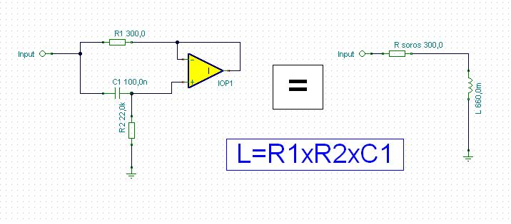
It means that we can use a very simple gyrator arrangement see below.
Ok, we are half ready. Now we have to figure out how to replace the actual coil with this. First we must bias our gyrator. Fortunately it is not as hard as it seems first. Note that the 4.7uF capacitor I mentioned earlier behaves like a shortcut to ground. It means that I can connect it to the gyrator's 22k resistor lower part as ground. In the other hand from DC point of view the capacitor upper part could be charged to 4.5V from the output of the first opamp via a 470k resistor. It is very similar to the original arrangement as the opamp's output acts the same role what the original transistor's collector, and the bias goes to the capacitor just like in the original and goes through the coil as here the gyrator. Then it finds it's way through the 1.5k resistor to the base of the transistor just like here to the input of the reduced amplifying opamp's input. See below how it is arranged.
 We are almost ready. Let's check its characteristic. The original Crybaby sweeps the 250Hz to 2000Hz range when you step on the pedal. This circuit is doing the same. Great. What it lacks is a magic factor, the Q. Q means quality here, actually Q has strong correlation with bandwidth of the bandpass filter, and the gain of the resonant frequency. Graphically I can describe Q as sharpness of the frequency characteristic curve.
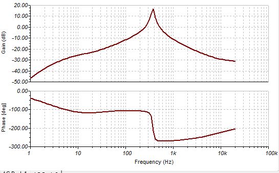
This is the frequency response of the original Crybaby at upper pedal setting (growl):
And see our circuit's with gyrator:
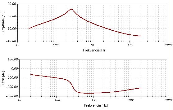
The difference is obvious. The gyrator has tenfold higher serial resistance than the original Crybaby's coil so the sharpness of the frequency characteristic is way worse. Also the amplification factor is weaker at resonance frequency.
This is the point when experimenters usually give up the idea of replacing the coil with gyrator.
Actually either I did it. I started to develop this circuit twenty four years ago. True, there was no Tina or other modeling software then and I had only a Sinclair ZX Spectrum computer in those years.
I have had Tina for seventeen years but I focused my efforts to special MOSFET power amplifiers. I have found what I seek in that subject so I turned my vision back to guitar effects. So I picked up the gyrator wah thread again. Fortunately my knowledge developed comparing to that I had at my first attempts. And now I already know tricks.
I do not deny, it is probably true that it is almost impossible to make a good crybaby with gyrator.
But again - I developed tricks. I managed to improve the qyrator circuit a little bit to get what I want.
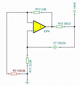
To understand this we must discuss the working method of our gyrator. So let's check again the scheme:
What we see is that there is a capacitor which is connected to the non inverting input of the opamp. Also we have a resistor here what is connected to the ground. As the frequency is increasing the resistance of the capacitor decreases so the signal at the non inverting input gets closer to the signal at the input of the whole circuit. Can you follow me?
So at higher frequencies the non inverting gate of the opamp follows better the original signal thus the output of the opamp does the same. It means that in high frequencies the signal is almost the same at the two end of R1. It means that the higher the frequency the lower current flows through R1. Great. It behaves just like coils.
So somehow I need to improve this attribute of our gyrator. Fortunately I can do that. The goal is that the circuit must keep its frequency response and should increase the current flow as expected. In this case from outer view the circuit would behave like it has less serial resistance because more current would flow by the same input signal.
The basic gyrator's opamp's gain is unity. If we turn it to higher than one then extra current has to flow through R1 due to the higher potential difference.
We have to be very careful. If the gain of the opamp becomes too much then the resistance of R1 will become virtually negative and the circuit will lose the ability to emulate coils.
I found that a very little rising in the gain effectively decreases the apparent serial resistance of our gyrator. Actually the gain factor here is 1.039. That does the trick.
That final values for the necessary 660 mH coil replacement and the configuration can be seen below:
Now let'see the frequency response.
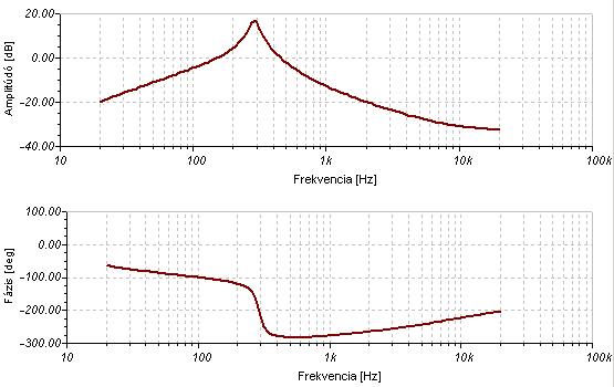
Well, that is quite good. The shape could be even better with precise tuning capacitor and resistor values but I think this result is still acceptable with these values. It really sounds like the original.
Now I complete three point of four. One remained, the optical tuning. Though mechanically it is way more simple than the cog wheeled potentiometer and practically noise free, in the other hand there are some disadvantages either.
All optical tuning circuit use photo resistors and LEDs. The problem is, that photo resistors are not perfect for controlling. They have relatively high resistance even at full illumination. Also their resistance is not enough high at full dark. Even they show some delay in following changes of illuminaton. Fortunately this delay is quite small and indifferent in our practice of tuning wah pedals.
So the main problem is the control range of resistance change is too narrow. Potentiometers are way better in this task. What to do now?
The solution is relatively simple, but we must understand first, how Crybaby tuning works.
I previously mentioned that the Crybaby circuit is actually a band pass filter. There are many bandpass filter topology, both active and passive. Crybaby is an active LC filter where the capacitor is tuned electrically. Filtering happens in front of the first electric component provided by passive components. The role of the active component ( transistor) is to amplify and to create reversed phase signal at the other end of the filtering capacitor (10n) to emulate higher capacitance - depending on the potmeter setting. The higher reversed phase signal gets to the second transistor the higher capacitance is showed by the capacitor from the emitter of this transistor.
So our goal is to control the signal level what gets from the collector of the first transistor to the base of the second transistor. Actually in the new circuit it means controlling the level of signal from the first opamp's output getting to the second one's input. Let me note that we use TL071 opamps (or a TL074 quad opamp IC) which have jFet inputs. What is important, we must control this signal totally. For higher frequencies we need to block entirely the signal getting to the second opamp. For low frequencies we need to pass the full signal to the second opamp. The limitations of photo resistors don't let them to be suitable for this requirement so we needed to find another solution. I decided to use a voltage divider, where the lower resistor is a junction FET. Its channel resistance can vary in extremely wide range from 500 ohm to Gigaohms depending on its gate-source bias voltage. It has minimal resistance between the drain and the source when gate-source voltage is zero or greater and maximal (practically infinite) when the gate source voltage around or less -2V.
So we can control this element by negative voltage. In the other hand we have positive voltage range from the ground to 9V so we create a virtual ground at 4.5V using an opamp which non inverting input is set to 4.5 V so its output is on the same voltage. In advance this virtual ground gives the correct bias for the whole Crybaby circuit so it has double usage.
Back to the signal control. We connect the controller jFet's source on the virtual ground (4.5V) so we can drive its gate by lower voltage in the lower 4.5V range of the original 9V supply voltage. Great. For the controlling voltage now we can use our photo resistor as a lower component of another voltage divider. Its lowest resistance in full illuminating is about 8 kohm. In total absence of light its resistance is about 500kohm. Thus we have to use a 10 kohm resistor as the voltage controller upper member. At full dark the photo resistor's resistance becomes 500 kohm thus the control voltage is almost 4.5V which is equal to the virtual ground's value which is the jFet source value also. In this case the FET is open and it shunts the signal to the virtual ground instead of letting it to the second opamp. In total illuminating the photo resistor's resistance is about 8 kohm which set the controller voltage to 2.25 V lower than the virtual ground voltage. It closes the jFet so it lets the signal pass to the second opamp. In intermediate setting part of the signal is shunted, other part is passed. Just like the potentiometer do in the original circuit.
After solving the problem of optical control I made three minor change. First I changed the 100k resistor which is paralel with the gyrator to 1M. It sharpens the bandpass curve a little bit.
Second I changed the first opamp configuration from inverting to non-inverting mode by choose its non-inverting input instead of the inverting one. Meanwhile I did the opposite with the second opamp because this circuit works only if the signal's phase is inverted before it gets to the 10n filtering feedback capacitor.
Third I put a source follover jFet stage before the whole circuit to avoid tone sucking what is an unpleasant disadvantage of basic crybaby circuit.
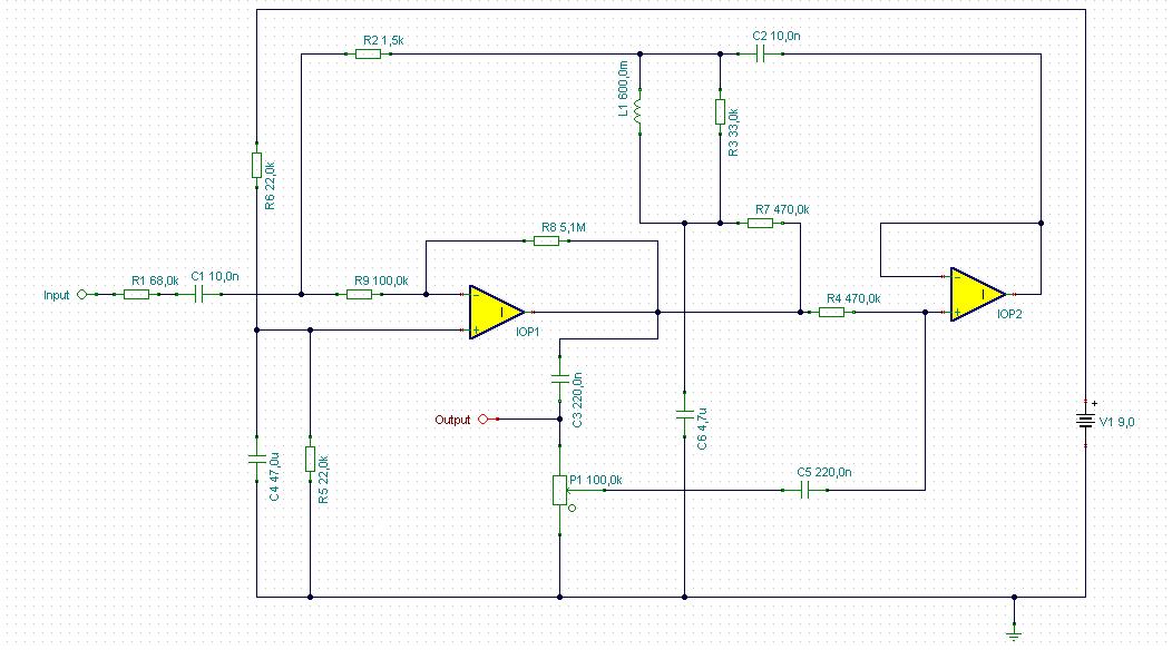
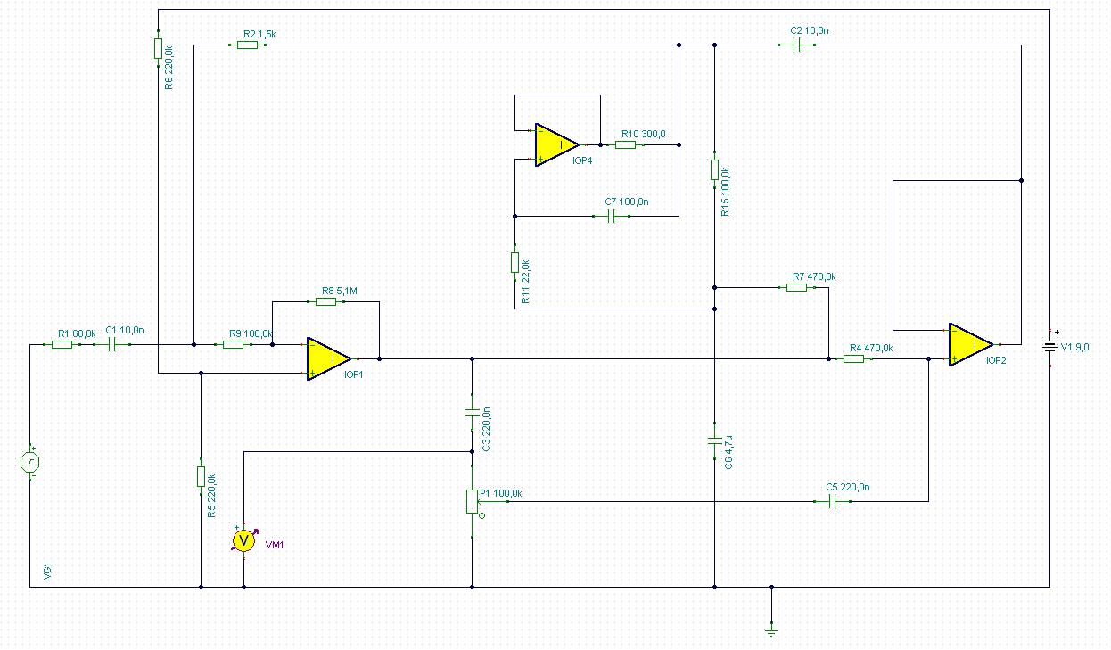
Now let's see the completed scheme:
This is a fully functioning circuit what sounds very close to the original Crybaby wah. Powered by 9V battery.
At last some words about optical tuning. As I mentioned above, it works by shadowing. Practically it means that we put the photo resistor into a black tube. At the other end of the tube there is a bright green LED. Yes, green due to the photo resistor's peak sensivity is at 540nm wavelength of light. That means we have to use green LED to provide such a light. During tuning we move a thin metal sheet between the LED and the photo resistor. It contains a triangle shaped hole. Depending on what part of the hole is between the two element different amount of light is blocked which drives the photo resistor's resistance. See below.
This is a fully functioning circuit what sounds very close to the original Crybaby wah. Powered by 9V battery. Good luck for constructing and sorry about my bad english.
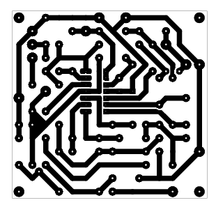
p.s. I am planning to publish the circuit board for this schematic, just don't know how to export size keeping pcb layout from my free pcb designer software. Anyway here is a mounting schem.


A bejegyzés trackback címe:
Kommentek:
A hozzászólások a vonatkozó jogszabályok értelmében felhasználói tartalomnak minősülnek, értük a szolgáltatás technikai üzemeltetője semmilyen felelősséget nem vállal, azokat nem ellenőrzi. Kifogás esetén forduljon a blog szerkesztőjéhez. Részletek a Felhasználási feltételekben és az adatvédelmi tájékoztatóban.
Lucas Sanchez Fellay 2020.08.15. 13:34:44
Thanks again, very good job and explanation.
Lucas,
Gazz 2020.09.08. 22:51:17